MicroProcess is a multi-level process mapping methodology. I’m using this method to map processes and workflows. In this article, I would like to share with you how I use this method to decouple complex and monolithic processes into an easy-to-follow, flexible and extendable multi-level process definition.
Thoughts
I’m passionate about drawing process diagrams. At one stage I was proud of showing people the complex and monolithic process flows I’ve drawn. However, along the compliments I received, I also found those process definition become an “art” instead of a “tool”. So I started to ask myself:
- How to make processes easy to follow for different user groups?
- How to present processes from general to particular?
- How to effectively put complex processes together? and
- How to effectively adopt changes in one part of a process definition but not impacting the other parts?
Making one piece of process diagram that is complex enough is definitely not the answer. What about a micro-process approach?
Approach
The approach I went with is a multi-level process mapping methodology, or to give it a name, a MicroProcesses. It breaks one level to multiple levels, and one process to multiple predefined processes. The levels and processes are connected together using predefined process links and navigation links. In the following sections, I’ll describe the details of this mapping method.
Guidelines
The design to certain extend aligns with the following guidelines/standards,
- TOGAF – Business Architecture – Process
- Business Process Model and Notation (BPMN)
- Microservices architecture
You may have noticed that I used words “to certain extend”, the reason being is that I want to align but not restrict this method in certain given frames. So here comes the details.
Get Started
Step 1
A picture worth a thousand words. Let’s use the picture below to start. The first step is to break one level into multiple levels.
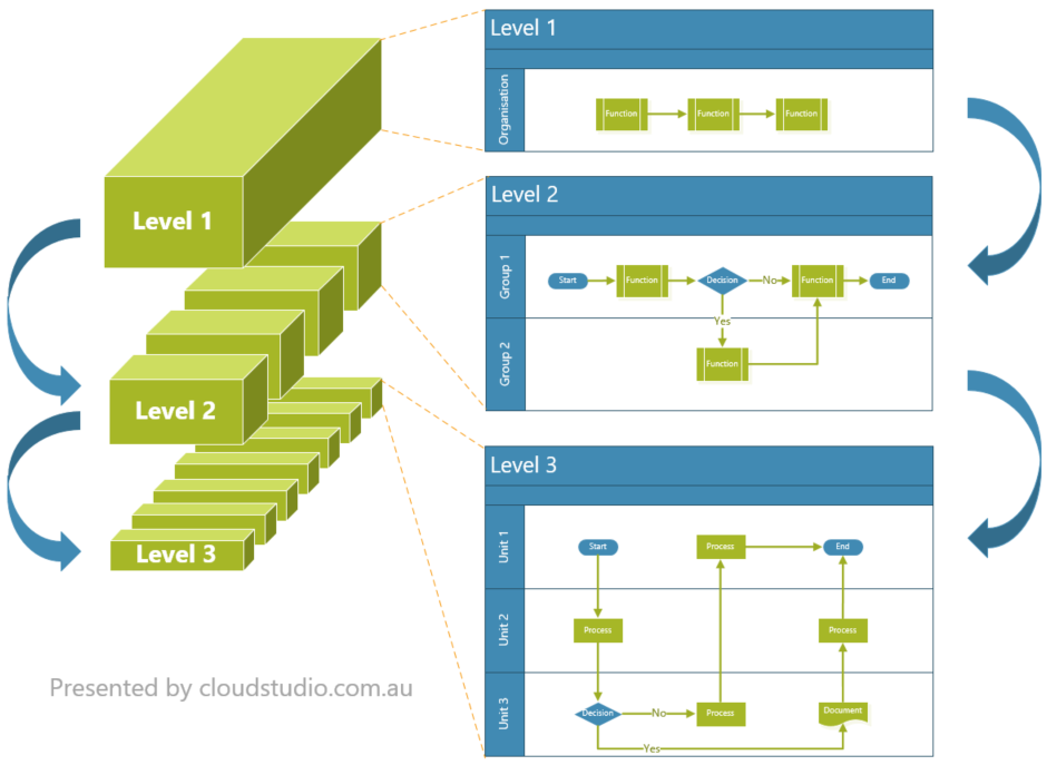
When mapping processes to different levels, keep the following things in mind,
- Who would be the audience for each level?
- How many levels you want to come up with?
- What you want to present on each level?
With the above questions clarified, you can combine them with the guidelines below to start structuring the multi-level process definition.
- If a group of steps repeatedly show up in multiple processes, group them out to a predefined process
- Try to fit each level of processes in a single A4 page ( better in portrait layout than landscape)
- Try not to go beyond four levels of processes
For the “portrait vs landscape” part, there may be different preferences. The reason why we recommend portrait is that process definition are often inserted into Word or PDF documents. A portrait-shaped process flowchart can easily fit in the existing portrait-layout documents.
For the “number of levels” part, there is no hard limit of how many levels can/should be defined to form an multi-level process definition. However, forming too many levels will add overhead on maintenance and impact user experience on navigation.
Having said the UX design on navigation, the Step 2 section below will provide more guidance.
Step 2
Once you have the multi-level structure designed, the next step is to ensure the orchestration and navigation is easy to follow. There are many ways to achieve this goal. Some recommendations are described below.
Call out the level number
From the process owner point of view, a multi-level process is like a “forest” with a number of “trees”. The process owner can see both forest and trees. However, from the audience point of view, some of them may only see “tree(s)”. To help the audience not lost in the forest, it’s recommended to mark each “tree” with a level number.
If you use Visio to define your processes, an example of level number is like below.
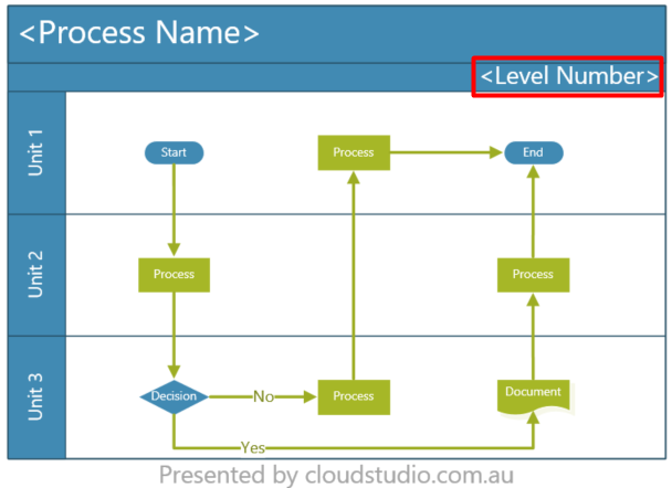
If you are using other process definition tools, try to embed the level number in an easy-to-find place, e.g. after the process name.
Add links on predefined processes
To help audience link a predefined process box at a higher level to a detailed process at a lower level, the process name must match. In addition, adding a link from the predefined process will improve the navigation experience.
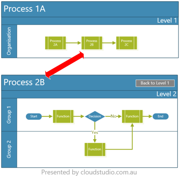
If you use Visio to define processes, you can insert an hyperlink in the predefined process box, and point the sub-address to the relevant Visio page. If you have process diagrams inserted across a Word document, try to create Hyperlink or Cross-reference within the document to link the parent and child processes together. If you have process diagrams inserted across online webpage(s), e.g. Confluence pages, try to use weblinks to cross reference the processes. Some plugins, e.g. Gliffy, can also empower you with embedding visio diagrams in Confluence pages and insert hyperlinks within the diagram.
Add Go Back buttons
The embedded links on predefined processes can help audience effectively drill down from parent levels to child levels. However, often audience may find hard to navigate back to the parent levels, especially after a few deep dives. To solve this issue, you can add a Go Back button on the child level process as below.
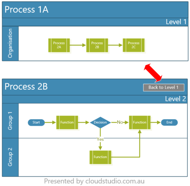
This way, audience can easily navigate back to the parent level where they came from.
Add process index
By adding links between parent and child level of processes are helpful for audience who have already navigated their way inside the “forest”. Another good addition to improve the UX on navigation is to show audience what are included in the “forest” before they enter it, which is to provide a process index upfront. Depends on where your processes are hosted, the way to index the content varies.
In Visio, the All button at the bottom of the UI (where the page tabs are located) is acting as an index. However, when you print the pages out, this OOTB index will not be presented. So it’s better to add a separate visio page at the beginning part to list out the pages/levels of processes. If you have your processed hosted in Word or PDF type of artifacts, similar approach can be used, e.g. adding an index page at beginning of the document. The same theory applies to web pages too.
Step 3
The content. Having a good microprocess structure is not the end of the story. The real value of a process definition is driven by whether it can provide valuable information and guidance to its audience. There isn’t any fixed structure for the content of process definitions as it always varies case by case. Having said that, there are some guidance, as below, can be used.
Similar to the guidance in the Step 1 section, think about who are the audience of your process definition. Put yourself in the audience’s shoes, and think about the following questions.
- Are the words used in the process definition mapping to BAU terms?
- Are there any jargons that people may not understand (e.g. the OOTB and BAU used above)?
- Have you jumped steps?
- Will the audience read your process once and throw it away?
You can expand the list with additional sanity check questions that you can come up with as well. And it’s recommended to ask the same questions to the reviewer of your process definition and seek their feedback.
With the above questions asked, you can combine the answers with the guidelines below to plant/expand “trees” in your “forest”.
- Try to use basic notation shapes
- Try to use simple language
- Try to use short sentences
- Try not to cross the sequence flow lines
Last but not least, please keep in mind that most processes will change. So it’s also important to build your microprocess structure and content to cater for subsequent changes.
Summary
The main objective of this article is not to make up a new word, i.e. microprocesses, but to help you structure your process definition in a multi-level process mindset. I hope you find this article useful.
As a reader, I prefer seeing pictures and bullet points in an article, so I used them throughout this article. Hopefully these diagrams and bullet points make sense.
If you have thoughts or questions, please feel free to share them in the comments.


Great Articles Richard, you got nice thing going here, best of luck mate
Richard:
Excellent article. I am currently developing an article on the use of SIPOC in process mapping based upon my past experiences and your explanation and examples of multistep process maps is one of the best I’ve seen.
By the way, there is a Visio plug-in called TaskMap that’s been around for nearly 20 years that hyperlinks between higher and lower level microprocesses exactly as you suggest in your article. Of course, Universal Process Notation (UPN) prescribes upper and lower-level task linking as well. In fact, TaskMap process notation and UPN are quite similar and were both created around the same time.